Mike,
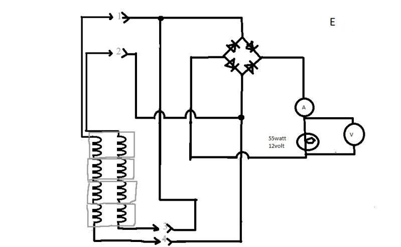
now, if you add a diode in line on each lead right where the numbers are,(#1, #2, #3, #4) to isolate each of them, there's no short.
I think something else would have to be done at the rectifier?
I'll try to draw it later, I have to go to work now.
Bruce
n-c alternator modifications: discussion and testing
Moderator: ajleone
-
ecurbruce
- Posts: 317
- Joined: Fri Apr 01, 2011 12:43 am
- Location: Hurricane mills TN
-
MotoMike
- Posts: 487
- Joined: Wed Aug 04, 2010 3:40 am
Re: 6volt or 12 volt?
Hi Bruce and Bob
thanks for that input.
My thought is that if I have chosen the phasing correctly, the ends that are tied together will be producing the same in phase voltages. So that if the points of connection each have 15 volts on them, there is no reason for current to pass between them. If the D cell analogy can be drafted again to represent a moment frozen in time, two batteries in paralell to provide the same voltage but with increased current handling ability.
Obviously if the phasing is wrong, a short exists and no current will go through the load, but plenty through the stators .
.
I have selected the phasing based on this observation. For the stock system to work, the two stator end connections must be 180 out of phase. If we look at the instant of time when the left stator output connection is max positive then the right stator output connection must be max negative. so if we then look at the point where the two are connected to ground in the stock circuit, the bottom of the left stator half must be more negative than the top of the left stator half. The bottom of the right must be more positive than the top right. I think these relationships tell us the phasing of the two stator halves. Thats the reasoning I used.
It would be prudent to put a fuse in one of the stator coil circuits. since we see about 5 amps in our testing so far and the coils can handle up to 10 amps, an 8 amp fuse should allow it to work if the phasing is correct and protect the stator if it is not.
Mike
thanks for that input.
My thought is that if I have chosen the phasing correctly, the ends that are tied together will be producing the same in phase voltages. So that if the points of connection each have 15 volts on them, there is no reason for current to pass between them. If the D cell analogy can be drafted again to represent a moment frozen in time, two batteries in paralell to provide the same voltage but with increased current handling ability.
Obviously if the phasing is wrong, a short exists and no current will go through the load, but plenty through the stators
I have selected the phasing based on this observation. For the stock system to work, the two stator end connections must be 180 out of phase. If we look at the instant of time when the left stator output connection is max positive then the right stator output connection must be max negative. so if we then look at the point where the two are connected to ground in the stock circuit, the bottom of the left stator half must be more negative than the top of the left stator half. The bottom of the right must be more positive than the top right. I think these relationships tell us the phasing of the two stator halves. Thats the reasoning I used.
It would be prudent to put a fuse in one of the stator coil circuits. since we see about 5 amps in our testing so far and the coils can handle up to 10 amps, an 8 amp fuse should allow it to work if the phasing is correct and protect the stator if it is not.
Mike
Last edited by MotoMike on Tue May 24, 2011 6:53 pm, edited 2 times in total.
-
MotoMike
- Posts: 487
- Joined: Wed Aug 04, 2010 3:40 am
Re: 6volt or 12 volt?
bob wrote:
____ I've already been thinking about that Mike,, but have held-back, waiting for test-results.
I'm thinking the low 1-ohm load-resistance is TOO low, thus making the alt.windings themselves act as a significant part of the total load-impedance.
MM
Clearly there is some effect exhibited due to the low ohmic value. Not sure what you mean about the stator windings being part of the load impedance. I'll have to think about that.
Here is my initial thought. the stock system will allow as low as .6 ohms of load before the fuse goes. So the system in stock configuration can handle one ohm and not be bothered by it. But if there is an opposing field condition at play here, maybe dropping down to one ohm allows the strength of these fields to become large enough, owed to the current through the stator coils to have a significant effect. In the stock system as we have mentioned, since only half the stator is used at a time, the strength of the fields generated from load current and their effect on the other stator half are of no concern.
-
wcorey
- Posts: 323
- Joined: Sun Jan 31, 2010 1:50 am
- Location: MA USA
Re: 6volt or 12 volt?
____ That's about 58-watts on one side and near 49.5 on the other, (so near 107.5w.DC total available power-juice for charging the modified system, [with the dual FW.rectifier set-up].
Still rather a disappointing result, from my particular practical perspective.
What concerns me is not so much the wattage but that at 6k it's just getting to the point where the voltage output will start charging a 12v battery. Obviously it wasn't designed/intended for that purpose, I'm sure it works great at 6v, also seems to put out substantially less heat than it's contemporary counterparts, another big plus. I'm very curious about the temp aspect as I know Mile is too, I have to wonder if some part of the seemingly unconventional design has taken it into consideration as a purposeful goal.
Bottom line, the modern stuff intended for 12v operation puts out more voltage at less than half the rpm (and lots of different rotor weights) so for me it's still the direction I'll likely stay in.
My next step there will probably be in figuring out how to down rate the outputs a bit. Another project for another day...
Bill
-
wcorey
- Posts: 323
- Joined: Sun Jan 31, 2010 1:50 am
- Location: MA USA
Re: 6volt or 12 volt?
Up and running again, as I suspected the centripetal mechanism for the starter winding was in a pile at the bottom of the motor, luckily didn't take out any winding with it. I now have to pull start it to get 3450 but no big deal.
You're all very fortunate to get this today as it *was* the first nice sunny day in a while and I was planning to take the bike for a spin but now looks like thunder storms coming in.
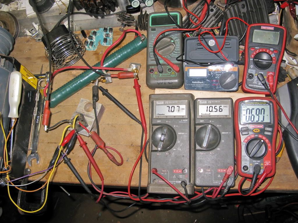
1ohm load 3450 rpm, 7.1a, 10.6vac, 6.9vdc
4ohm load 3450 rpm, 2.9a, 15.4vac, 11.9vdc
5ohm load, 3450 rpm, 2.4a 15.8vac, 12.2vdc
7 ohm load, 3450 rpm, 1.8a, 16vdc, 12.7vdc
Bill
You're all very fortunate to get this today as it *was* the first nice sunny day in a while and I was planning to take the bike for a spin but now looks like thunder storms coming in.
1ohm load 3450 rpm, 7.1a, 10.6vac, 6.9vdc
4ohm load 3450 rpm, 2.9a, 15.4vac, 11.9vdc
5ohm load, 3450 rpm, 2.4a 15.8vac, 12.2vdc
7 ohm load, 3450 rpm, 1.8a, 16vdc, 12.7vdc
Bill
Last edited by wcorey on Fri Jul 29, 2011 5:40 pm, edited 4 times in total.
-
MotoMike
- Posts: 487
- Joined: Wed Aug 04, 2010 3:40 am
Re: 6volt or 12 volt?
oops again
Last edited by MotoMike on Tue May 24, 2011 9:51 pm, edited 1 time in total.
-
MotoMike
- Posts: 487
- Joined: Wed Aug 04, 2010 3:40 am
Re: 6volt or 12 volt?
wcorey wrote:Up and running again, as I suspected the centripetal mechanism for the starter winding was in a pile at the bottom of the motor, luckily didn't take out any winding with it. I now have to pull start it to get 3450 but no big deal.
You're all very fortunate to get this today as it *was* the first nice sunny day in a while and I was planning to take the bike for a spin but now looks like thunder storms coming in.
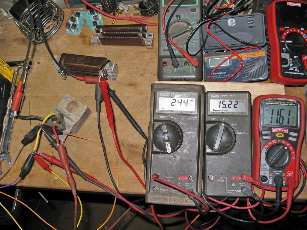
3 ohm load, 3450 rpm, 2.9a, 15.2vac, 11.6vdc (Just realized looking at the pic the current is reading on ac, took another spin on dc and revised the figure but didn't take another corrected pic.)
Bill
Thanks Bill, you are the champ.
In this setup the stator halves are operating in true parallel. common voltage but circuit current is the result of adding the current through the stators, so each half is lighter loaded. My thought was that with each half splitting the current load, that we might see the output voltage be higher. At any rate, each stator half is working less than if getting your output from one coil. I know goes without saying.
If you get to it, I'd be curious to see the same circuit at the same rpm with different ohmic loads.
I don't suppose anyone is spread sheeting these results. I'm having trouble keeping them all straight.
All this testing makes me wonder how Bevel Bobs' setup squares with our data. If I understand correctly, he is operating the stator in series fashion after lifting the ground and taking the output across a Podtronics full Wave R/R He mentions that he keeps it spun up, but I doubt he is cranking it at 6 k all the time and yet keeps his battery well charged with a wattage load that must be higher than stock.
Mike
-
wcorey
- Posts: 323
- Joined: Sun Jan 31, 2010 1:50 am
- Location: MA USA
Re: 6volt or 12 volt?
"
(<EDIT> I've gone back and updated/fixed the original post to reflect my failure to communicate. Didn't alter this one as it would only confuse the content of this post )
Hah! that was a test to see if anyone was really following what I was doing and to see if I was making sense. I think with the high traffic it was overlooked by everyone.
The post was on page 11, right after the very first set of pics. I put up the pics (of a setup that was being discussed at the time) with only rpm to see if anyone would look at them and be able to discern exactly what was going on by using my description of the setup from the previous post. It still may be useful info.
No one took the bait...
It was in response to this request from you and Bruce;
The following is what I posted, and it's still a test keep in mind that the wiring colors are from the original scheme/description (testing done at 2 ohm)
<edit> pics deleted...
I've put together a 3 ohm load and generated new single winding test data with it. I tried both a parallel and ('normal' and alternate) series connection scheme (and posted the results of the series schemes in cryptic photo form which no one seemed to notice ). "
____ Huh, I haven't seen it ! _ What page (of what thread) is it on ??
(<EDIT> I've gone back and updated/fixed the original post to reflect my failure to communicate. Didn't alter this one as it would only confuse the content of this post )
Hah! that was a test to see if anyone was really following what I was doing and to see if I was making sense. I think with the high traffic it was overlooked by everyone.
The post was on page 11, right after the very first set of pics. I put up the pics (of a setup that was being discussed at the time) with only rpm to see if anyone would look at them and be able to discern exactly what was going on by using my description of the setup from the previous post. It still may be useful info.
No one took the bait...
It was in response to this request from you and Bruce;
" run the jumper between 1 and 3, and connect to the rectifier 2 and 4. It's still series,
Will it make a difference? "
____ Perhaps both you & Bill had missed that I had already suspected that Bill may have already done so inadvertently (if all 4 of his wire-leads are the same color).
The following is what I posted, and it's still a test
These pics will give me an indication if my previous post was intelligible and yes, I'm playing games...
<edit> pics deleted...
Last edited by wcorey on Fri Jul 29, 2011 6:52 pm, edited 3 times in total.
-
wcorey
- Posts: 323
- Joined: Sun Jan 31, 2010 1:50 am
- Location: MA USA
Re: 6volt or 12 volt?
Here's the revised setup with some standard test data to go along with it.
Bob, you can use it to add to the new thread as you see fit.
<EDIT> 4 ohm loads were formerly erroneously labeled 3 ohm.
The two standard output wires from the stator (1 and 2) are the black cord , with a black and a white conductor.
The added wires (3 and 4, formerly grounded to the stator core when in stock form) are the yellow ones (one has a black stripe). (all coming out of the alternator at 8 o'clock and draped over the grey motor)
The other end of the black wire (through it's set of coils/windings) is yellow/black.
The white wire (coil/winding set) has the plain yellow on it's other end.
(since 1,2,3 and 4 aren't color coded on the drawing, the two pairs are interchangeable in my descriptions)
The black wire has an orange jumper connection,
the white has a yellow jumper,
the yellow has grey
and the black/yellow has purple.
In summary, the orange and purple are two opposite ends of one set of windings, yellow and grey are the other set.
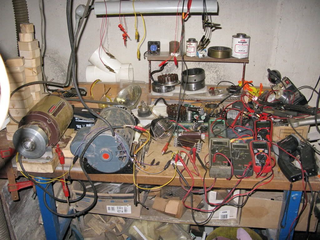
When looking at the photo's, it should be possible to determine the stator wiring scheme by the colors and placement, as well as the test data results by the meter outputs.
It may even be possible to determine rpm by whether or not the belt can be seen on the grey motor (top left in most pics), belt on, 6k rpm, belt off, 3450 rpm.
Loads are tougher, as the resistor values and connection scheme can't be seen, the big green one is 1 ohm and the stack of 4 flat brown ones is 3 ohm.
Values reported are rounded to the nearest single decimal point.
single winding, 4 ohm, 3450 rpm, 2.8a, 14.7vac, 11.2vdc
single winding, 4 ohm, 6k rpm, 4.8a, 24.7vac, 19vdc
both windings, series, 4 ohm, 3450 rpm, 3.8a, 19.1vac, 15vdc
both windings, series, 4 ohm, 6k rpm, 4.7a, 23.3vac, 18.6vdc
Bill
Bob, you can use it to add to the new thread as you see fit.
<EDIT> 4 ohm loads were formerly erroneously labeled 3 ohm.
The two standard output wires from the stator (1 and 2) are the black cord , with a black and a white conductor.
The added wires (3 and 4, formerly grounded to the stator core when in stock form) are the yellow ones (one has a black stripe). (all coming out of the alternator at 8 o'clock and draped over the grey motor)
The other end of the black wire (through it's set of coils/windings) is yellow/black.
The white wire (coil/winding set) has the plain yellow on it's other end.
(since 1,2,3 and 4 aren't color coded on the drawing, the two pairs are interchangeable in my descriptions)
The black wire has an orange jumper connection,
the white has a yellow jumper,
the yellow has grey
and the black/yellow has purple.
In summary, the orange and purple are two opposite ends of one set of windings, yellow and grey are the other set.
When looking at the photo's, it should be possible to determine the stator wiring scheme by the colors and placement, as well as the test data results by the meter outputs.
It may even be possible to determine rpm by whether or not the belt can be seen on the grey motor (top left in most pics), belt on, 6k rpm, belt off, 3450 rpm.
Loads are tougher, as the resistor values and connection scheme can't be seen, the big green one is 1 ohm and the stack of 4 flat brown ones is 3 ohm.
Values reported are rounded to the nearest single decimal point.
single winding, 4 ohm, 3450 rpm, 2.8a, 14.7vac, 11.2vdc
single winding, 4 ohm, 6k rpm, 4.8a, 24.7vac, 19vdc
both windings, series, 4 ohm, 3450 rpm, 3.8a, 19.1vac, 15vdc
both windings, series, 4 ohm, 6k rpm, 4.7a, 23.3vac, 18.6vdc
Bill
Last edited by wcorey on Fri Jul 29, 2011 5:42 pm, edited 3 times in total.
-
ecurbruce
- Posts: 317
- Joined: Fri Apr 01, 2011 12:43 am
- Location: Hurricane mills TN
Re: 6volt or 12 volt?
First, I want to thank you,Bill for all of your hard work! This thread has progressed leaps & bounds because of your efforts. There are lots of numbers to crunch and analize, particular interesting to me is the difference in the 1 ohm readings and the 3ohm readings.
Today I decided is the day to get to the bottom of alternator coil anatomy... As we know there are four coil assemblies ( two larger ones, and two smaller ones) on the narrow case alternator. Each of these coils has two separate windings, which end up in separate series circuits. I removed one of the larger coil assemblies and found; there are four layers of winding with 22 turns each, two of the layers comprise one circuit of the coil , then a layer of paper, then two more layers of windings comprise the other circuit of the coil.All of the winding is wound counter clockwise ( both circuits). Copper winding size is .030, don't know gague size conversion. The smaller coil assemblies have four layers of windings with 14 turns each, (I'm assuming all wound counterclockwise as well, I'm not unwinding one of them).
AS a side note, these coils did not come from the alternator that I'm using in my motor.
Ends up to be about 25 feet of wire total on the larger coil. Tomorrow I may decide to unwind one of the smaller coil assys., cause now I'm not 100% sure that it's wound counterclockwise.
Last edited by ecurbruce on Wed May 25, 2011 12:53 am, edited 1 time in total.
Return to “Ducati Singles Main Discussions (& How to Join)”
Who is online
Users browsing this forum: Google [Bot] and 38 guests