n-c alternator modifications: discussion and testing

Ducati single cylinder motorcycle questions and discussions, all models. Ducati single cylinder motorcycle-related content only! Email subscription available.
Moderator: Morpheus

Moderator: ajleone

DewCatTea-Bob
Posts: 2897
Joined: Sun Nov 01, 2009 10:53 am
Location: Near SE side of Lake Michigan

Re: 6volt or 12 volt?

Postby DewCatTea-Bob » Tue May 24, 2011 2:46 am

PLEASE STAND-BY WHILE I COMPLETE THIS RESPONSE-POST.

By: wcorey...
Life got busy on me the last couple days...

____ Don't be concerned about it Bill, (it's not like this is your work-job), if you only achieved one step per week, we'd be jerks to not appreciate each step you manage to get accomplished !


" I've been still pondering on how to proceed with the testing and organization of such, "

____ Within THIS thread, it ought not matter too much Bill, as everything can get straightened-out in the dedicated thread for your test-work. - (Which I hope you've noticed!)
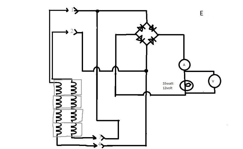
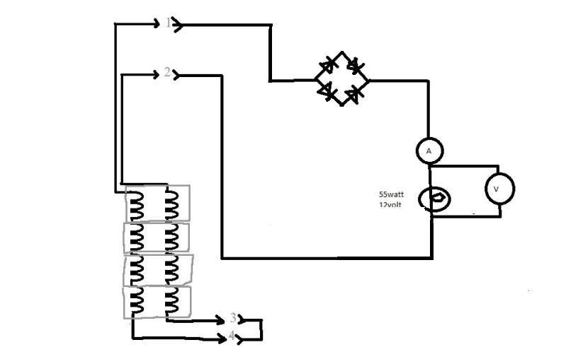
__ I think a logical progression would be to start-out with obtaining the power-output results of the stock-type set-up - (which is connecting-up the parallel-pair -[consisting of alt.winding & diode, (x2)], and measuring their combined [half-waves] output). _ (As depicted in the related diagram-scheme I've provided.)
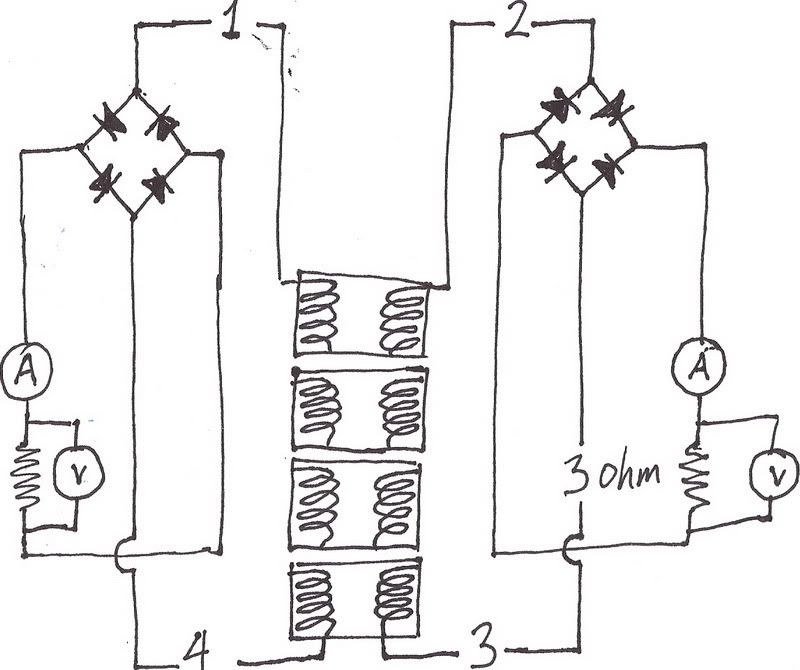
Then next test-step (with all following done in 'half-wave rectification'), each alt.winding alone,, then next, with both windings in (standard/original)- 'series',, then next, with both in (reversed)- 'series'.


" If I'm going to put in all this effort, I don't want to compromise and confuse it by skipping a few details. "

____ Good attitude Bill ! _ I will try to make sure you don't skip-over any steps that would otherwise put things in an out of order sequence, (and hopefully others will point-out anything else I've so omitted). _ (I now see that Bruce has already introduced the final test, expected in the rectification-sequence.)


" I believe we need some work on terms and nomenclature, an example as in Bob's concern with my inconsistent use/understanding of the terms 'cores', 'coils', 'windings', etc. "

____ I sure wasn't concerned with your picked wording specifically Bill ! ...
Someone such as myself understands what you & Mike must really mean to say, but those who're just learning can get completely confused when we don't all use our terms exactly the same way EVERY time ! _ (And it's this consideration that's behind my own word-extension efforts.) _ Without such consideration, it's always an added puzzle to figure if another's wording has been hastily-picked OR purposely-chosen ! _ And when ya have to guess at that, it's likely a sure road to misinterpretation.
So I say, that if ya really wish to be properly understood, then proof-read what ya've written and correct/replace any hastily picked words.


" and the concern with 'counter electromotive force'. "

____ It's been my understanding that when electricity produces magnetic-flux, or when magnetic-flux creates electricity, (for motors & generators, etc), that's to do with 'Electo-Motive Force' -('EMF'),, and when a single-core creates magnetic-flux in opposite directions -(both N & S) at the same time, then I think it's fair to indicate: "Counter", with the results of course tending to be a cancellation-effect.


" For the sake of standardization, I have yet again switched wires around on the test setup, realizing that the original stator output wires should be the yellow/orange and not the opposite 'tag ends' (that are now purple/grey). "

____ That's good ! _ Cuz when I first read what you had had them colored as, I thought either I may not have understood correctly, or you didn't type what you really had meant, and if you did indeed mean it that way, I thought that that's going to make things confusing. _ So I'm glad you got the idea to put it more logically, on your-own !
__ So do you now have it so one alt.winding has a yellow-wire and a purple-wire, while the other has an orange-wire and a gray-wire ?


" The load resistors are all 3ohm 55w, the bottom one is in series with the other three that are all in parallel. "

____ According to this wording, you have four 3-ohm resistors arranged for a total of 4-ohms, (since three of them in 'parallel', equate to 1-ohm total). _ And that 1-ohm in series with the 4th 3-ohm resistor, makes the total of 4-ohms !
So is that correct, Bill ?


" I would also like to have one of you do a revision of the 'stator, load and rec.block' version of Mikes drawing (that most details of requests for testing would/should be based upon); "

____ Yes sir, I'll try to have such presented below (near bottom of this post).


" Add a +/- to the rec.block, add the wire color scheme to the outputs along with the 1-4, update the load spec. and somehow add the current, vac and vdc meters so they can be easily moved around. "

____ Don't know if I can manage all that (yet). _ However, for the half-wave rectification testing, diode polarity is irrelevant.


" I could do it but I haven't had time to figure out the complicated photoshop I have and it's a time consuming pain to use while 'winging it'. "

____ Don't worry about it Bill, you're spending enough time & carrying enough of the-load as it is !


" Ideally I'd like each of you to generate a version of the drawing that shows the wanted/intended setup, then I can post a pic of the test results and summary of the data to go along with it. "

____ That would indeed be the ultimate way to present each test outcome, most orderly !


" This is from Bob's post and is ok except needs the aforementioned revisions and it and the written description still left me figuring out where to put the vac meter. "

____ The AC.volt-meter always goes across the AC.power-source output-connections.

Image

"So this should be the drawing implemented, except the current and vac meters are not in the drawing. "

____ The current-meter IS in the drawing... It's represented by the circle with the 'A' shown inside, as the A stands for Amps !
And the amp-reading remains the same, regardless of where it's connected (between ANY two components) !

'
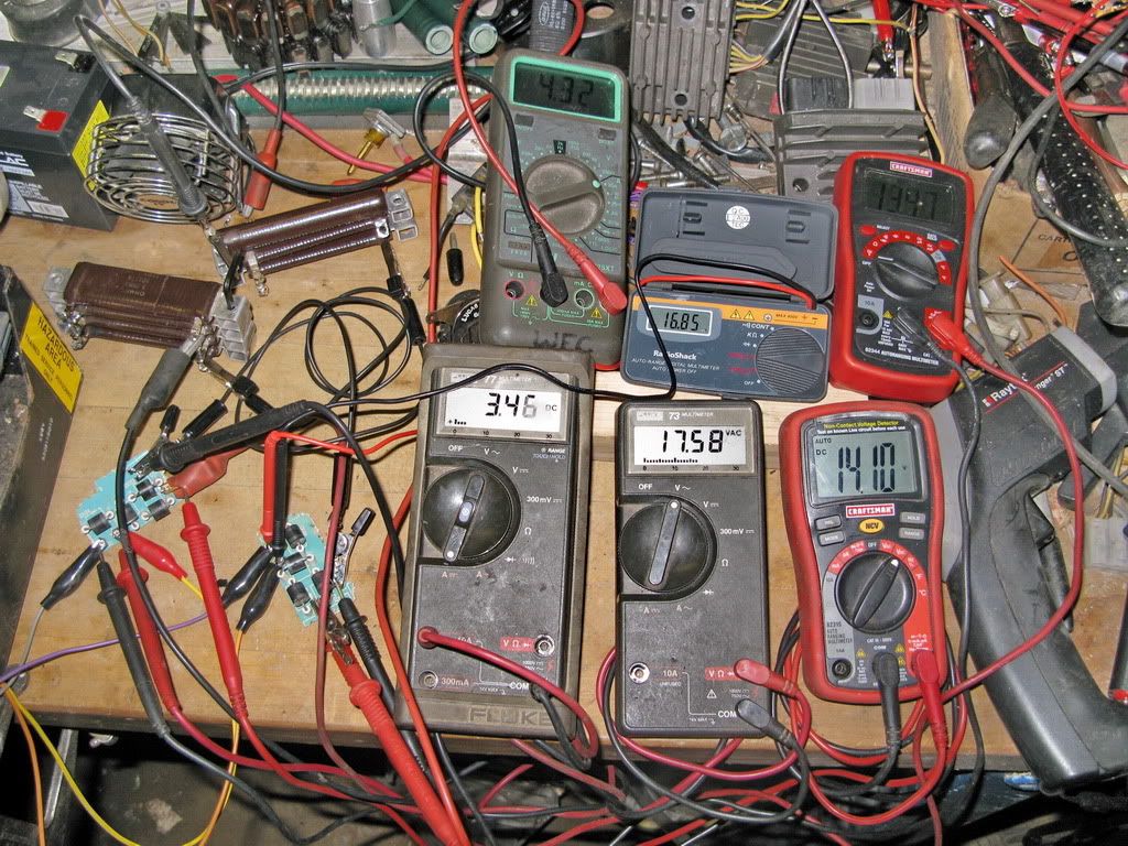
" Half wave rectification', 3 ohm load, 3450 rpm, 2.2a, 25.2vac, 8.8vdc "

____ That then indicates a wattage-output of near 28w-AC & near 19.5w-DC.


" I'm not sure whether to start a new post or just edit them into the the existing one. "

____ If you have any 'corrections', then 'edit' them-in, and make note of it,, otherwise start separate posts (so that any single post doesn't get too large).


" I would like some direction/preferences as to the sequential order which the data sets (pictures) should be placed, or maybe I should just put them up however and the rearrange them as requested. "

____ Well in THIS thread, it seems they're already going up in random-order, so the final-presentation-order can be straightened-out within the dedicated-thread.


Fun-Cheers,
-Bob
You do not have the required permissions to view the files attached to this post.
PLEASE NOTE... If this-post is not-yet signed-off with '-Bob', then I'm still in the process of completing it,, and if not also included with 'DCT' near bottom as well, then I may edit this post's wording at a later time. - Dct.Bob

DewCatTea-Bob
Posts: 2897
Joined: Sun Nov 01, 2009 10:53 am
Location: Near SE side of Lake Michigan

Re: 6volt or 12 volt?

Postby DewCatTea-Bob » Tue May 24, 2011 3:02 am

By: ecurbruce...
" I wish drawing were larger. "

____ Your drawing is fine enough Bruce, it can be clicked-on to enlarge !


" I hope this makes sense to you guys "

____ It's obvious Bruce, that you've figured where these testing-steps were heading towards.


Tillater,
-Bob
PLEASE NOTE... If this-post is not-yet signed-off with '-Bob', then I'm still in the process of completing it,, and if not also included with 'DCT' near bottom as well, then I may edit this post's wording at a later time. - Dct.Bob

MotoMike
Posts: 487
Joined: Wed Aug 04, 2010 3:40 am

Re: 6volt or 12 volt?

Postby MotoMike » Tue May 24, 2011 3:46 am

DewCatTea-Bob wrote:
Here's a link back to it... viewtopic.php?f=3&t=556&start=70#p4192

thanks bob

MotoMike
Posts: 487
Joined: Wed Aug 04, 2010 3:40 am

Re: 6volt or 12 volt?

Postby MotoMike » Tue May 24, 2011 4:03 am

ecurbruce wrote:here's a test that I think will tell if there is flux field interaction or show the effect of counter electromotive force.
This would be a test of simultanous isolated series circuits. Alternator windings with leads 2 and 3 would be wired setup like Mike's drawing "c", with a (with a 1 ohm resistor instead of light bulb,)
Then at the same time alternator windings with leads 1 and 4 also would be setup like Mike's drawing "c" , run to a separate rectifier and 1ohm resistor.
When spinning at 34oo rpm, if there is no change in the specifications (8.4 amps, 12.2vac, 9.2 vdc) from the previous test of one set of windings (Mike's drawing "c"), that would indicate the absence of flux field interaction effect. If there is a change in the specifications, it would indicate flux field interaction .

disregard the 3 ohm resistor in the drawing, it should be 1 ohm. I was lucky to get what I did in there! I wish drawing were larger.
I hope this makes sense to you guys with more "official and organized" training than myself, it's hard for me to explain these ideas without the professional jargon.


good job Bruce. check your diode polarities, I think you got some backwards.

that will be the interesting test. I think that I know what will happen, but the unexpected results thus far have given me pause. If there is a change then the question is pretty surely answered. but if there is not, how do we account for the change in the series connected stator when loaded?

After that test, I would be curious about the following. Sorry about the lack of color Bill. terminals 3 and 4 are the ones that were formerly grounded in the stock alternator.
Image
Last edited by MotoMike on Tue May 24, 2011 4:28 am, edited 1 time in total.

wcorey
Posts: 323
Joined: Sun Jan 31, 2010 1:50 am
Location: MA USA

Re: 6volt or 12 volt?

Postby wcorey » Tue May 24, 2011 4:13 am

First come, first served...

Image

Scrounging can be an art. Sorry about the mess, pretty tough to follow, but you can get the general idea. Wasn't planning on doing this one so soon but good to get it over with, lol.
Anyone wanting any variations on this, now is the time...

'One side' 1 ohm load, 3450 rpm, 4.2a, 7vac, 4.8vdc
'The other side', same load/rpm, 4.3a, 7.2 vac, 4.9.vdc


'One side' 3 ohm load, 6k rpm, 4.3a, 16.8 vac, 13.5vdc
'The other side', same load/rpm, 3.5a, 17.6vac, 14.1vdc

Image

Hit a little bump in the road... While up at 6k rpm something made a 'bad noise', :shock:, we who play with motors all know the type of sound. At first I though it was the alternator but thankfully it turned out to be the driven motor, it has ceased to function. Guess it didn't appreciate life in the fast lane, no surprise really, it's what happens when you push things well past what they're designed to do. It was a mickey mouse setup anyway, was kind of a nice motor though, 'borrowed ' it from my jointer.
Lucky to get the data from the run at least. Guess I'll have to do what I really wanted to avoid and take the time to make a dedicated arbor to spin the rotor. Haven't investigated or thought about what that will entail, not up for dealing with it at the moment.
I have some still 'unpublished' data that I can post up in the meantime and you guys can ruminate on what we have so far...


Bill
Last edited by wcorey on Fri Jul 29, 2011 6:14 pm, edited 3 times in total.

MotoMike
Posts: 487
Joined: Wed Aug 04, 2010 3:40 am

Re: 6volt or 12 volt?

Postby MotoMike » Tue May 24, 2011 4:36 am

:shock: :shock: :o :o

Bill you are a miracle worker. Man, I'd love to go through your stash ;)


I got to hit the hay.

later
Mike

wcorey
Posts: 323
Joined: Sun Jan 31, 2010 1:50 am
Location: MA USA

Re: 6volt or 12 volt?

Postby wcorey » Tue May 24, 2011 4:54 am

Dammit Bob, you did in another of my posts! Figure out what you're doing and then stop doing it.... Aaarg....

Bill

DewCatTea-Bob
Posts: 2897
Joined: Sun Nov 01, 2009 10:53 am
Location: Near SE side of Lake Michigan

Re: 6volt or 12 volt?

Postby DewCatTea-Bob » Tue May 24, 2011 5:06 am

____ So very sorry about that Bill ! _ (Good-thing you weren't all-done with it completely, anyhow.)
Still very sorry though !

" Anyone wanting any variations on this, now is the time... "

____ Yes Bill, how about the very-same setup, except replace the 1-ohm loads with greater resistances from 3 to 10 ohms each, (and it doesn't really matter if both sides have the same resistance-load values).


SORRY-Cheers,
-Bob
PLEASE NOTE... If this-post is not-yet signed-off with '-Bob', then I'm still in the process of completing it,, and if not also included with 'DCT' near bottom as well, then I may edit this post's wording at a later time. - Dct.Bob

DewCatTea-Bob
Posts: 2897
Joined: Sun Nov 01, 2009 10:53 am
Location: Near SE side of Lake Michigan

Re: 6volt or 12 volt?

Postby DewCatTea-Bob » Tue May 24, 2011 5:21 am

By: wcorey...
" 'One side' 1 ohm load, 3450 rpm, 4.2a, 7vac, 4.8vdc
'The other side', same load/rpm, 4.3a, 7.2 vac, 4.9.vdc "

____ That's about 20-watts on one side and 21-watts on the other, (so 41w.DC total power-juice available for charging the [modified]- system).


" 'One side' 3 ohm load, 6k rpm, 4.3a, 16.8 vac, 13.5vdc
'The other side', same load/rpm, 3.5a, 17.6vac, 14.1vdc "

____ That's about 58-watts on one side and near 49.5 on the other, (so near 107.5w.DC total available power-juice for charging the modified system, [with the dual FW.rectifier set-up].


" Lucky to get the data from the run at least. "

____ That's so true, cuz it has given us the chance to figure the rate-of-increase (between 3450 & 6k-RPM).


" Guess I'll have to do what I really wanted to avoid and take the time to make a dedicated arbor to spin the rotor. "

____ That would only be needed if we still needed to do the higher RPM testing.
Whatever RPM your other motor spins at, ought do for what testing is left.


Hopeful-Cheers,
-Bob
PLEASE NOTE... If this-post is not-yet signed-off with '-Bob', then I'm still in the process of completing it,, and if not also included with 'DCT' near bottom as well, then I may edit this post's wording at a later time. - Dct.Bob

DewCatTea-Bob
Posts: 2897
Joined: Sun Nov 01, 2009 10:53 am
Location: Near SE side of Lake Michigan

Re: 6volt or 12 volt?

Postby DewCatTea-Bob » Tue May 24, 2011 5:53 am

" If there is a change then the question is pretty surely answered. but if there is not, how do we account for the change in the series connected stator when loaded? "

____ I've already been thinking about that Mike,, but have held-back, waiting for test-results.
I'm thinking the low 1-ohm load-resistance is TOO low, thus making the alt.windings themselves act as a significant part of the total load-impedance.


" I would be curious about the following. "

Image[/quote]

____ Mike, after just a quick look at your hook-up scheme, it seemed fairly clear that it MAY contain a short-circuit, (depending on the actual polarity of the two stator-windings relative to each other.) ...
Your presented scheme could be bad in a specific manor. ...
__ If we think of the two stator-windings as D-cells both setting upright, then they will feed the obvious short-circuit (rather than go-through the load at all),, and if ONE cell is up-side-down, then the two cells will be in a combo parallel/series circuit-arrangement, both feeding the load together.
(So there's a 50% chance that such a D-cell circuit-arrangement could simply short-out.)
However the no-load voltage-measurements seem to indicate that the two stator-windings are arranged so as to avoid the short-circuit circuit possibility.
____ Just observational notes.

-Bob
PLEASE NOTE... If this-post is not-yet signed-off with '-Bob', then I'm still in the process of completing it,, and if not also included with 'DCT' near bottom as well, then I may edit this post's wording at a later time. - Dct.Bob


Return to “Ducati Singles Main Discussions (& How to Join)”

Who is online

Users browsing this forum: No registered users and 33 guests