Eldert,
you're right in theoretical a way. But it is impractical in reality.
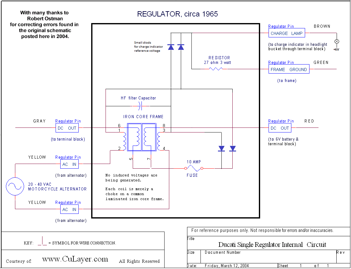
In the schematics shown above, the ground connection of the alternator coil set's center tap is missing, as it is internally soldered to the alternator base plate:
alt_fig.jpg
This kind of recifier system is called "dual half-wave". It can also be found in many transformer-equipped line power-supplies of electrical gear.
Each winding branch oder half conducts current through the diode, which "sees" a positive AC half wave, while it's counterpart is blocked by the other diode due to the AC's negative voltage polarity. So indeed, only one half of the alternator produces power at a time.
One might think, why not connect the two alternator branches in a way which can double the power? Well, you can desolder the windings center tap and leave it unconnected. This puts the 2 winding halfs into "serial mode", hence doubling the terminal voltage. But - it's an AC source, with resistance and imaginary "impedance" (i.e. inductance). Furthermore, the inductances of the alternator half are wound on the same iron cores, in turn are not acting independantly, but form a cross-coupled or so called "mutual" inductance. The result: you get ~twice the output voltage, but the alternators output power stays more or less constant, the max. current is reduced.
Btw, desoldering the center tap in the N/C alternators, or disconnecting it from the battery+ in the W/C system is the well known way to convert both systems to 12 Volts. The two single diodes then have to be subsituted by a bridge ("Graetz") rectifier.
Hans
EDIT: a good explanation of the different rectifier system is given here:
https://www.electricaltechnology.org/2019/01/what-is-rectifier-types-of-rectifiers-their-operation.html