By: ecurbruce...
" Each lead would need to run through it's own diode to isolate it. "
____ Which is just what the stock black-box includes for doing so !
Dukaddy-DUKEs,
-Bob
n-c alternator modifications: discussion and testing
Moderator: ajleone
-
DewCatTea-Bob
- Posts: 2897
- Joined: Sun Nov 01, 2009 10:53 am
- Location: Near SE side of Lake Michigan
Concerning Parallel Rectification
PLEASE NOTE... If this-post is not-yet signed-off with '-Bob', then I'm still in the process of completing it,, and if not also included with 'DCT' near bottom as well, then I may edit this post's wording at a later time. - Dct.Bob
-
wcorey
- Posts: 323
- Joined: Sun Jan 31, 2010 1:50 am
- Location: MA USA
Re: 6volt or 12 volt?
DewCatTea-Bob wrote:__To get the 'half-wave' output-power for testing, you can simply use your FW.bridge-block by ignoring it's AC-inputs, and simply wire-up your (series-type circuit) to it's Plus & Minus terminals, (which will incidentally maintain the two-diode voltage-drop, as before).
wcorey wrote: I don't understand this... wouldn't you have to use one ac input on the rectifier?
DewCatTea-Bob wrote:____ Doing that would be okay too, but then you'd be making use of only one diode...
Using a single diode would keep your circuit as simple as possible but I figure your existing rect.block is already handy & up to the needed current-handling capacity.
By connecting the entire rect.block (as I've suggested) just makes continued use of it simple, as it's then doing same as if one BIG diode. - (As circuit-wise, there's two parallel diode-pairs -[consisting of 2 diodes in series].) _ So the rect.block's 4 diodes are doing that which one diode alone would do, anyhow.
I'm still missing something here, just being dense I guess. I'm reading it like I'm supposed to ignore both yellow (ac) rect.block wires and hook the stator outputs to the red and black ( +-)? The load then goes where?
Seems like simple stuff to explain but I suppose you'll have to spell it out with drawings and circles and arrows, maybe Mike can modify one of his drawings to reflect it.
____ That is no doubt certainly the case with the stock (positive DC only, operation) circuit setup, and MAY indeed even remain to be the case with the DC only SERIES operation (which I've requested to be tested).
So please also spell out which setup scheme is this? What goes where? We have nice pics and drawings to refer back to and make thing clear, please utilize them...
So, other than the above, what's next?
I've put together a 4 ohm load and generated new single winding test data with it. I tried both a parallel and ('normal' and alternate) series connection scheme (and posted the results of the series schemes in cryptic photo form which no one seemed to notice
I'm ready to roll, just need a direction to go... Who wants what? The most coherent instructions get done first...
" the designers were not concerned with this as they are only using half of the coils at a time and these interactions won't exist. "
I don't get this either, the magnets on the rotor line up with all the stator coils simultaneously. How does it 'select' which half works when? I know it alternates between polarities but it's still 'using' all the coils on every pulse.
Bill
Last edited by wcorey on Fri Jun 03, 2011 1:40 am, edited 1 time in total.
-
DewCatTea-Bob
- Posts: 2897
- Joined: Sun Nov 01, 2009 10:53 am
- Location: Near SE side of Lake Michigan
Further Testing - Half-wave Rectification of Alt.windings
By: wcorey...
" I'm reading it like I'm supposed to ignore both yellow (ac) rect.block wires and hook the stator outputs to the red and black ( +-)? The load then goes where? "
____ Since we wish to switch-over from full-wave rectification to half-wave rectification, you need to unhook the AC-outputs (from the FW.rect-block's AC-inputs),, THEN reconnect ONE of the alternator's outputs to the Plus-side (or Minus-side, [as it doesn't matter one way or the other]), of your rect.block. _ Then the opposite-corner terminal of your rect.block is connected to the load, then the load's opposite-side is connected to the alternators remaining wire-lead. _ That then thus creates a three component series-circuit arrangement (between the alternator & rectifier & load). _ (The rect.block's AC-inputs are both left unused since we're now using it only as a simple half-wave rectifier.)
__ (After you've used your best ability to comprehend the intended circuit from my written-word alone, THEN check your mental-conclusion against the pic/diagram I've added way-down below, [that goes for all readers].)
__ So that means the 'alternator' gets connected to the 'rectifier' (on one side), and the 'load' on it's other side,, and with the load & rectifier also connected to each-other, thus a small circle/series-circuit, (like 3 kids all holding hands,[lol]) _ (And your ammeter can be connected anywhere between any of those three component/connections,, with volt-meter connected across the load.)
" So, other than the above, what's next? "
____ Perhaps before that, you should leave both the alternator's stock/(original-yellow) wire-lead connections hooked-up to the rect-block's AC-inputs, and do a test on the load, with the load connected between the rect.block's Pos.terminal and the alternator's (two, normally grounded) stator lead-ends. _ (Note Neg.terminal on rect.block to be ignored.)
As this test would tell us how much power the stock charging-system makes (before the stock-regulator jams/weakens it) !
(I've added a pic/diagram indicating the desired circuit-scheme, down (nearer) below.
" I've put together a 3 ohm load and generated new single winding test data with it. I tried both a parallel and ('normal' and alternate) series connection scheme (and posted the results of the series schemes in cryptic photo form which no one seemed to notice ). "
____ Huh, I haven't seen it ! _ What page (of what thread) is it on ??
(* Mike, I hope you aren't once-again going to confuse things by claiming that it's really "full wave", as I hope you now understand why that would make things too confusing!)
__ Also Bill, it seems you've misunderstood Mike's use of the word "coils", as he had actually meant: 'alt.stator-windings', not core-coils,, (am I not right about that Mike?).
I think you guys should adopt & stick to my terminology, cuz I'm the only one who uses logically-named terms and keeps them fairly consistently used ! _ (As "coils"-[alone, for example], can mean too many different things !)
Hopeful-Cheers,
-Bob
" I'm reading it like I'm supposed to ignore both yellow (ac) rect.block wires and hook the stator outputs to the red and black ( +-)? The load then goes where? "
____ Since we wish to switch-over from full-wave rectification to half-wave rectification, you need to unhook the AC-outputs (from the FW.rect-block's AC-inputs),, THEN reconnect ONE of the alternator's outputs to the Plus-side (or Minus-side, [as it doesn't matter one way or the other]), of your rect.block. _ Then the opposite-corner terminal of your rect.block is connected to the load, then the load's opposite-side is connected to the alternators remaining wire-lead. _ That then thus creates a three component series-circuit arrangement (between the alternator & rectifier & load). _ (The rect.block's AC-inputs are both left unused since we're now using it only as a simple half-wave rectifier.)
__ (After you've used your best ability to comprehend the intended circuit from my written-word alone, THEN check your mental-conclusion against the pic/diagram I've added way-down below, [that goes for all readers].)
____ We'd like to test each alt.winding alone (one at a time), and then both alt.windings in series, (both standard, &, with one reversed).wcorey wrote:DewCatTea-Bob wrote: and MAY indeed even remain to be the case with the DC only SERIES operation (which I've requested to be tested).
So please also spell out which setup scheme is this? What goes where?
__ So that means the 'alternator' gets connected to the 'rectifier' (on one side), and the 'load' on it's other side,, and with the load & rectifier also connected to each-other, thus a small circle/series-circuit, (like 3 kids all holding hands,[lol]) _ (And your ammeter can be connected anywhere between any of those three component/connections,, with volt-meter connected across the load.)
" So, other than the above, what's next? "
____ Perhaps before that, you should leave both the alternator's stock/(original-yellow) wire-lead connections hooked-up to the rect-block's AC-inputs, and do a test on the load, with the load connected between the rect.block's Pos.terminal and the alternator's (two, normally grounded) stator lead-ends. _ (Note Neg.terminal on rect.block to be ignored.)
As this test would tell us how much power the stock charging-system makes (before the stock-regulator jams/weakens it) !
(I've added a pic/diagram indicating the desired circuit-scheme, down (nearer) below.
" I've put together a 3 ohm load and generated new single winding test data with it. I tried both a parallel and ('normal' and alternate) series connection scheme (and posted the results of the series schemes in cryptic photo form which no one seemed to notice ). "
____ Huh, I haven't seen it ! _ What page (of what thread) is it on ??
____ Well Mike was only in reference to the stock-system, which uses only half-wave* diode-rectifiers which only work half the time, so the two diodes (seemingly working together) "'select'" which alt.winding's current-juice is allowed to enter the system, and only "when" the current-juice being offered happens to be 'positive' (from either alt.winding).wcorey wrote:MotoMike wrote:the designers were not concerned with this as they are only using half of the coils at a time and these interactions won't exist.
I don't get this either, the magnets on the rotor line up with all the stator coils simultaneously. How does it 'select' which half works when? I know it alternates between polarities but it's still 'using' all the coils on every pulse.
(* Mike, I hope you aren't once-again going to confuse things by claiming that it's really "full wave", as I hope you now understand why that would make things too confusing!)
__ Also Bill, it seems you've misunderstood Mike's use of the word "coils", as he had actually meant: 'alt.stator-windings', not core-coils,, (am I not right about that Mike?).
I think you guys should adopt & stick to my terminology, cuz I'm the only one who uses logically-named terms and keeps them fairly consistently used ! _ (As "coils"-[alone, for example], can mean too many different things !)
Hopeful-Cheers,
-Bob
You do not have the required permissions to view the files attached to this post.
PLEASE NOTE... If this-post is not-yet signed-off with '-Bob', then I'm still in the process of completing it,, and if not also included with 'DCT' near bottom as well, then I may edit this post's wording at a later time. - Dct.Bob
-
MotoMike
- Posts: 487
- Joined: Wed Aug 04, 2010 3:40 am
Re: 6volt or 12 volt?
So far the results of the series connected stators are still a mystery to me. "
____ That would be expected if ya continue to consider the 6-pole alt.stator as same as a normal/standard center-tapped transformer, (which has a continuously-wrapped winding with a third wire-connection 'tapped' somewhere in-between the single-winding's ends).
__ In the past I've not fully contested that notion because I've never un-wound a stock-stator to see just exactly how they had their winding-turns originally 'wound'.
So there still exists the possibility that the two windings which I've maintained are "separate", may not be wound (around the common-core) in the very-same manor.
MM
I guess I missed Bills readings where he put the stator windings in series and tested them unloaded. Still not finding it. But if the voltage output is essentially double, then we are seeing the potential felt across the whole winding with no path for current. since the voltage doubled this tells us that they are arranged so that the potentials across each coil are arranged in series per the D cell battery analogy. This unloaded potential which most consider voltage is what some consider electromotive force is induced across the stator by the rotatin magnetic field from the rotor. We are not seeing the effects of voltages induced by current passing through them to a load, because there is no current passing through them yet. And since the voltage drops to near the single half stator value when a current path is provided through a load, The drop in voltage must be due to opposing fields being created in the coils wound on common cores from that current through the path provided through the load. In short, no they are not wound as a traditional center tapped transformer. So I believe Bob is correct in that opinion.
-
MotoMike
- Posts: 487
- Joined: Wed Aug 04, 2010 3:40 am
Re: 6volt or 12 volt?
from Bob containg comments from Bill and Mike
MM
the designers were not concerned with this as they are only using half of the coils at a time and these interactions won't exist.
Bill
I don't get this either, the magnets on the rotor line up with all the stator coils simultaneously. How does it 'select' which half works when? I know it alternates between polarities but it's still 'using' all the coils on every pulse.
____ Well Mike was only in reference to the stock-system, which uses only half-wave* diode-rectifiers which only work half the time, so the two diodes (seemingly working together) "'select'" which alt.winding's current-juice is allowed to enter the system, and only "when" the current-juice being offered happens to be 'positive' (from either alt.winding).
(* Mike, I hope you aren't once-again going to confuse things by claiming that it's really "full wave", as I hope you now understand why that would make things too confusing!)
__ Also Bill, it seems you've misunderstood Mike's use of the word "coils", as he had actually meant: 'alt.stator-windings', not core-coils,, (am I not right about that Mike?).
I think you guys should adopt & stick to my terminology, cuz I'm the only one who uses logically-named terms and keeps them fairly consistently used ! _ (As "coils"-[alone, for example], can mean too many different things !)
Bob I was referring to the stock set up, I figured that is the only one the designers would have been concerning themselves with.
Bill I don't get that you misunderstood what I meant by coils, or which setup I was refering to - the stock set up. I gather that you just want an explanation about how only half of the coils are used at a given time in the stock configuration.
the magnets do induce voltage across all the coils at the same time. but current is allowed to flow only through the half of the stator whose voltage forward biases it's associated diodes(one to provide system power and one to operate the charge light). While those are forward biased, the diodes associated with the other half of the stator are reverse biased and acting like an open so that no path for current exists in the other half of the stator. With no current through this path and no field created, the voltage limiting we are expeiencing was not a consideration.
I think the full wave /half wave discussion has been adequitely beaten to death and nothing we've discovered here changes that.
Last edited by MotoMike on Mon May 23, 2011 11:53 pm, edited 1 time in total.
-
MotoMike
- Posts: 487
- Joined: Wed Aug 04, 2010 3:40 am
Re: 6volt or 12 volt?
Bob's post with comment from MM at the top:
The cause would certainly be from the field caused by the current flow though both coils on a common core at the same time. "
____ Right, 'AC' current-flow (most likely) however.
And since we must be talking OPPOSING flux-fields during higher AC current-flows, I consider such as falling-under the term 'Counter Electro-Motive Force'. _ (Please correct me if you know of a more specific term for such.)
MM
Don't know why you thought I might be saying it was DC current, but yes AC.
I don't have a problem with you calling it counter electro- motive force. I don't think it is incorrect to do so. I just felt that opposing voltage could be used and we would not keep introducing yet another term. And yes it is used in generators and motors, but also batteries and just about any source that creates a difference of potential that can cause current to flow. But if you want to get back to using it in it's original context, it was to describe the potential across a battery that can cause current to flow. A difference of potential that causes current to flow is voltage.
-
MotoMike
- Posts: 487
- Joined: Wed Aug 04, 2010 3:40 am
Re: 6volt or 12 volt?
" One thing that is niggling away at me is Bills revelation that the alternator heats significantly with no load. "
____ Should only be flux-field interaction, right?
not sure if you mean flux field from different causes interacting or the flux field from the rotating magnetic field interacting with the core material. If the latter, then yes.
____ Should only be flux-field interaction, right?
not sure if you mean flux field from different causes interacting or the flux field from the rotating magnetic field interacting with the core material. If the latter, then yes.
-
wcorey
- Posts: 323
- Joined: Sun Jan 31, 2010 1:50 am
- Location: MA USA
Re: 6volt or 12 volt?
Life got busy on me the last couple days...
I've been still pondering on how to proceed with the testing and organization of such, If I'm going to put in all this effort, I don't want to compromise and confuse it by skipping a few details.
I believe we need some work on terms and nomenclature, an example as in Bob's concern with my inconsistent use/understanding of the terms 'cores', 'coils', 'windings', etc.
and the concern with 'counter electromotive force'.
For the sake of standardization, I have yet again switched wires around on the test setup, realizing that the original stator output wires should be the yellow/orange and not the opposite 'tag ends' (that are now purple/grey).
The load resistors are all 3ohm 55w, the bottom one is in series with the other three that are all in parallel. I may flip the bottom one around to make the connection scheme more obvious in the pics.
I would also like to have one of you do a revision of the 'stator, load and rec.block' version of Mikes drawing (that most details of requests for testing would/should be based upon);
Add a +/- to the rec.block, add the wire color scheme to the outputs along with the 1-4, update the load spec. and somehow add the current, vac and vdc meters so they can be easily moved around.
I could do it but I haven't had time to figure out the complicated photoshop I have and it's a time consuming pain to use while 'winging it'.
Ideally I'd like each of you to generate a version of the drawing that shows the wanted/intended setup, then I can post a pic of the test results and summary of the data to go along with it.
The following is just for an example;
This is from Bob's post and is ok except needs the aforementioned revisions and it and the written description still left me figuring out where to put the vac meter.
So this should be the drawing implemented, except the current and vac meters are not in the drawing.
'Half wave rectification', 4 ohm load, 3450 rpm, 2.2a, 25.2vac, 8.8vdc
<edit> 4ohm load is a correction, was mistakenly labeled 3 ohm.
Bill
Last edited by wcorey on Fri Jul 29, 2011 6:11 pm, edited 2 times in total.
-
DewCatTea-Bob
- Posts: 2897
- Joined: Sun Nov 01, 2009 10:53 am
- Location: Near SE side of Lake Michigan
Re: 6volt or 12 volt?
____ Well Mike, you must've seen that post of Bill's, cuz you did acknowledge that you were "trying to pay attention" (in your follow-up post).MotoMike wrote:MMDewCatTea-Bob wrote:MotoMike wrote:So far the results of the series connected stators are still a mystery to me.
____ That would be expected if ya continue to consider the 6-pole alt.stator as same as a normal/standard center-tapped transformer, (which has a continuously-wrapped single-winding with a third wire-connection 'tapped' somewhere in-between the single-winding's ends).
__ In the past I've not fully contested the notion (that the alternator may be considered as same), because I've never un-wound a stock-stator to see just exactly how they had their winding-turns originally 'wound'.
So there still exists the possibility that the two windings (which I've maintained are "separate"), may not be wound (around the common-core) in the very-same manor.
I guess I missed Bills readings where he put the stator windings in series and tested them unloaded. Still not finding it.
Here's a link back to it... viewtopic.php?f=3&t=556&start=70#p4192
PLEASE NOTE... If this-post is not-yet signed-off with '-Bob', then I'm still in the process of completing it,, and if not also included with 'DCT' near bottom as well, then I may edit this post's wording at a later time. - Dct.Bob
-
ecurbruce
- Posts: 317
- Joined: Fri Apr 01, 2011 12:43 am
- Location: Hurricane mills TN
Re: 6volt or 12 volt?
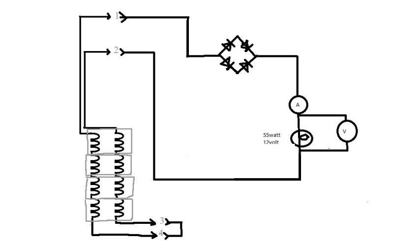
here's a test that I think will tell if there is flux field interaction or show the effect of counter electromotive force.
This would be a test of simultanous isolated series circuits. Alternator windings with leads 2 and 3 would be wired setup like Mike's drawing "c", with a (with a 1 ohm resistor instead of light bulb,)
Then at the same time alternator windings with leads 1 and 4 also would be setup like Mike's drawing "c" , run to a separate rectifier and 1ohm resistor.
When spinning at 34oo rpm, if there is no change in the specifications (8.4 amps, 12.2vac, 9.2 vdc) from the previous test of one set of windings (Mike's drawing "c"), that would indicate the absence of flux field interaction effect. If there is a change in the specifications, it would indicate flux field interaction .
disregard the 3 ohm resistor in the drawing, it should be 1 ohm. I was lucky to get what I did in there! I wish drawing were larger.
I hope this makes sense to you guys with more "official and organized" training than myself, it's hard for me to explain these ideas without the professional jargon.
You do not have the required permissions to view the files attached to this post.
Return to “Ducati Singles Main Discussions (& How to Join)”
Who is online
Users browsing this forum: No registered users and 36 guests