How to repair a "slipping" kick starter on a narrow case engine.
This worked for me, your results may vary.
Here's an excerpt from "Ducati Singles Restoration":
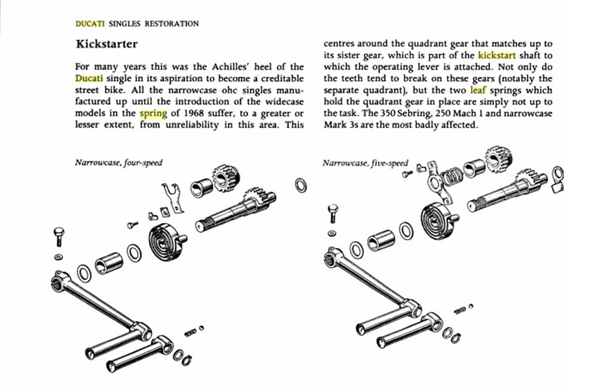
This is a little misleading. The drawing on the left entitled "Narrowcase, four-speed"depicts the problematic forked leaf spring that is held in place with a single bolt at the bottom:
![]()
The drawing on the right entitled "Narrowcase, five-speed" depicts the problem-solving coil spring that is held in place over the coil with a "bridge" that is secured in two places, above and below the coil spring:

Another problem with the text is that both early four-speed and early five speed engines came with the faulty leaf spring. Also it's not that there are two leaf springs as the text could be interpreted, but rather the single leaf spring is forked and thus presents two leaf tines. Some people have been known to attempt a kick start repair by installing a pair of the forked leaf springs back-to-back, as sort of a laminated arrangement to gain more spring rigidity. I had one such 250 that came to me with a pair of springs, but that had failed to solve the problem.
The rest of this page is an attempt to tell you how to convert a slipping kick-start lever by switching from the forked leaf spring to the bridged coil spring.
First off you need to secure a bridge and coil spring. I gather that later narrowcase engines came with these. Some vendors like DesmoPro sell all the components you need in a kit. There is a kit for four-speed and a kit for five-speeds. The difference is in the length of the top bolt and the length of the spacer that top bolt passes through. Order the correct kit for your bike.
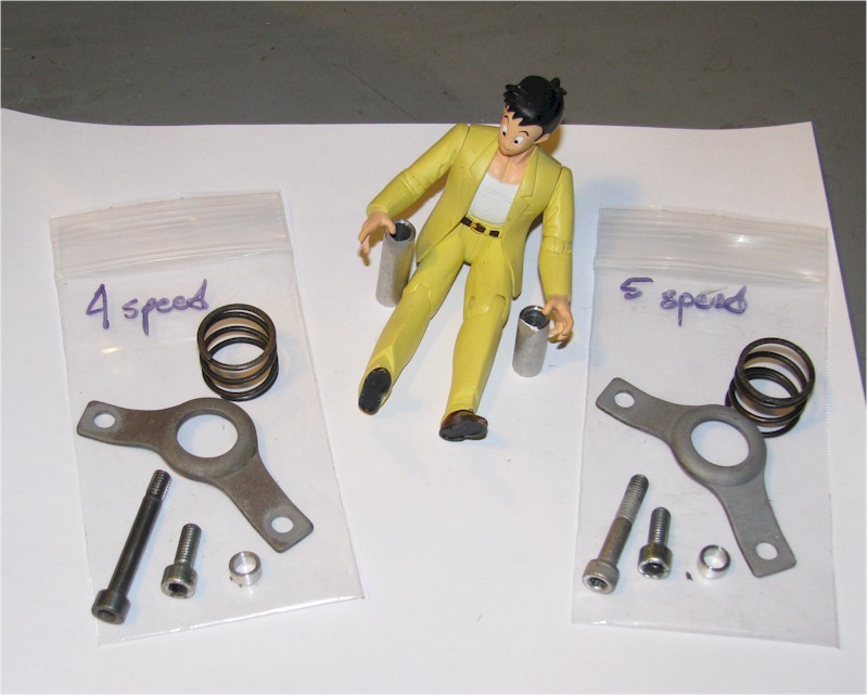
Four-speed kit and Five speed kit
Once you have the kit you need proceed as follows:
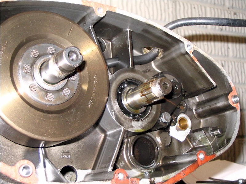
Take off the kick start lever:
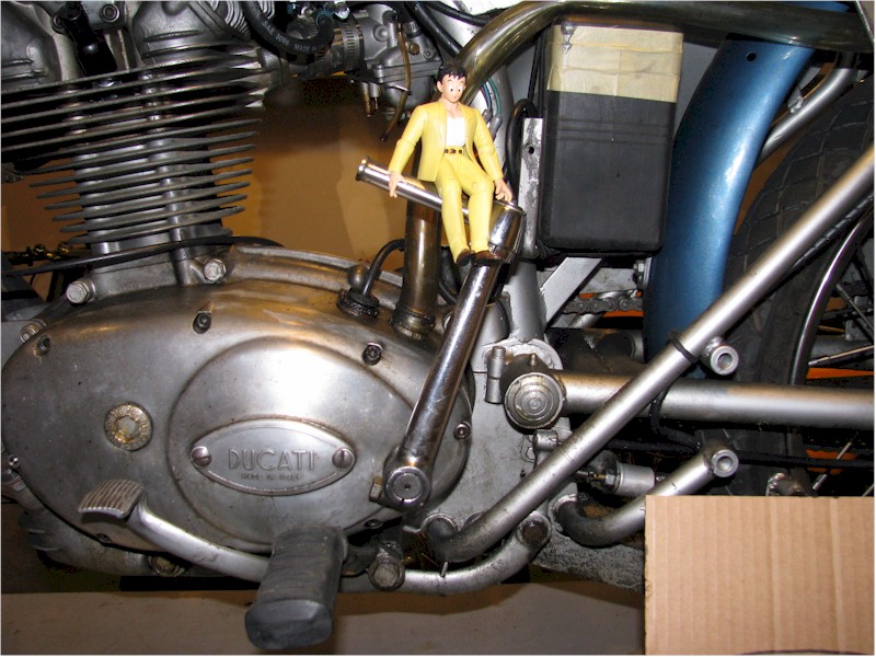
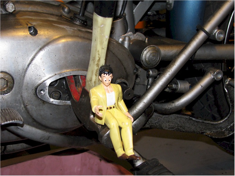
Lower the foot peg to give yourself room to take the engine side cover
off: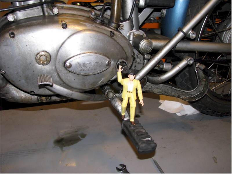
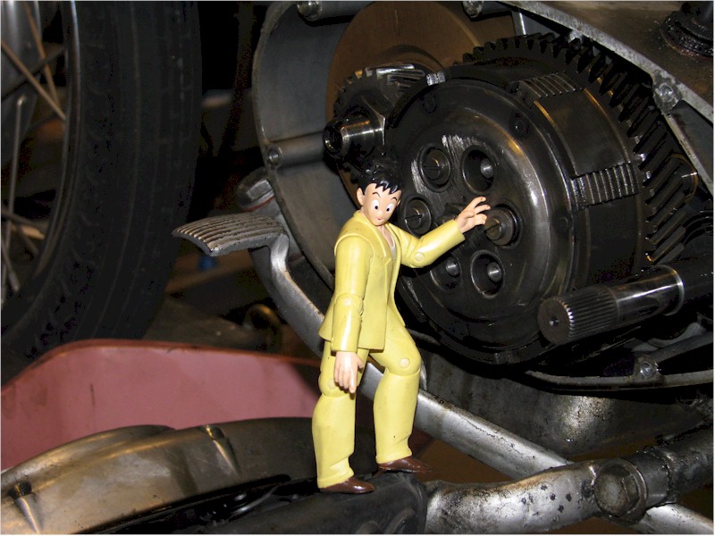
Remove the clutch inspection cover:
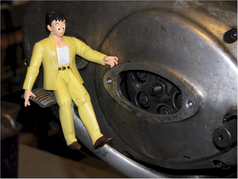
Remove the bolts that secure the engine cover to the cases:
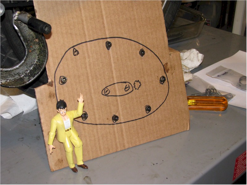
The bolts are different lengths. Think about drawing a
position map on a piece of cardboard and poking the bolts through to make
re-assembly less problematic:
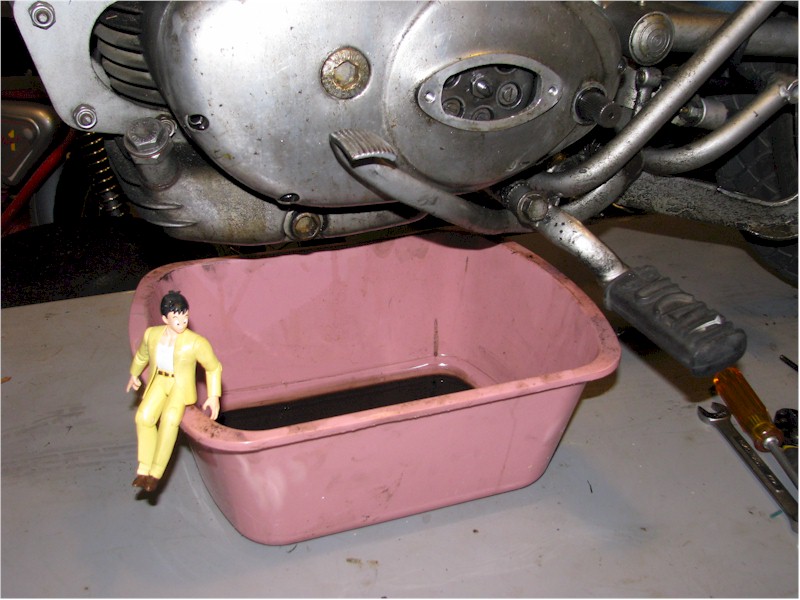
Place a pan under the engine cover as a small amount of oil
will be expelled when the cover is removed:
Use a claw hammer in the clutch inspection cover to pull the
engine cover horizontally away from the engine case:
Remove the clutch springs:
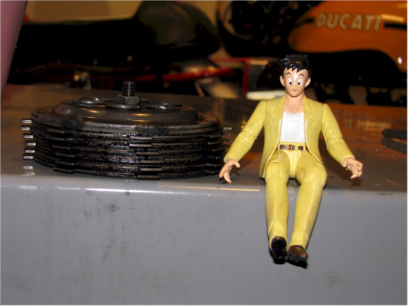
Remove the clutch disks that make up the clutch pack:
Remove the ball bearing that you see in the center of the
clutch.
Now it's time to remove the nut that holds the clutch inner
and outer hub in place. You have some choices here. Some people use
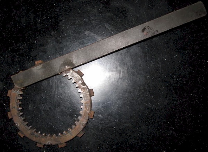
a clutch holding tool which can be purchased or one can be fabricated out of old
clutch plates.
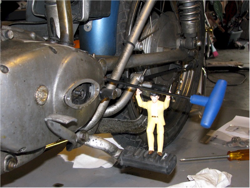
If you choose to use a clutch holding tool, a friend of the
forum strongly cautions against using the kick start shaft to secure the handle
when removing the clutch nut. It can break the engine boss around the kick
start shaft:

Interlude... you should find a locking tab holding the clutch hub nut. I did not and so I have no photographic record of me bending it back prior to removing the clutch nut. Straighten the locking tab so the nut can be removed.
I chose to stuff shop rags between the inner an outer clutch
hubs, making sure that the cloth was tightly packed in the slots of both hubs:

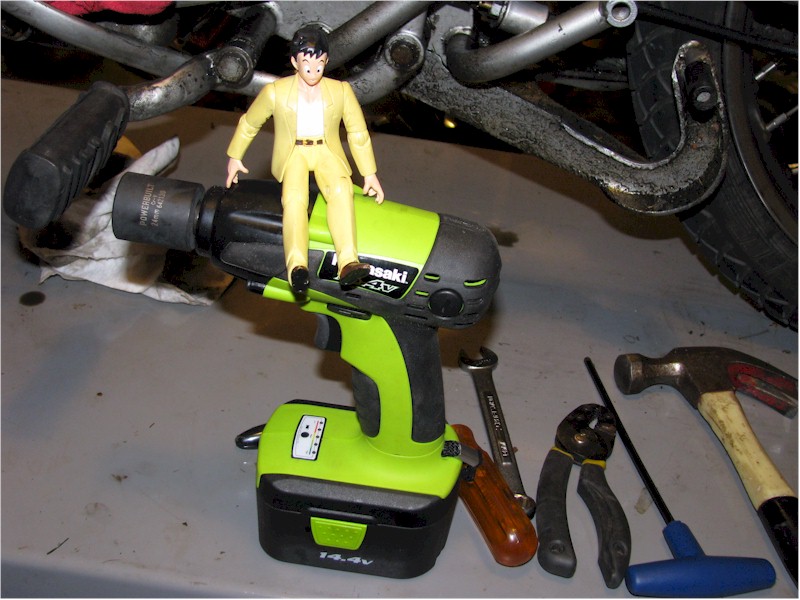
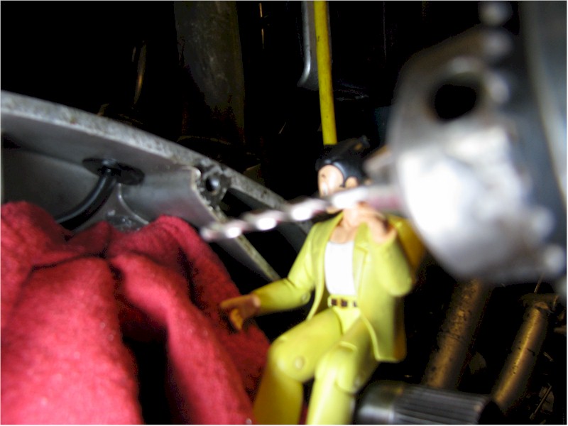
You are going to want to use an impact gun to remove the
clutch hub nut. It is a conventional (not reverse) threaded nut. It spins
off quickly and easily with an impact gun.
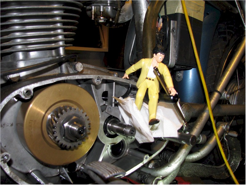
With the clutch hub nut removed you can remove the small
center clutch hub:
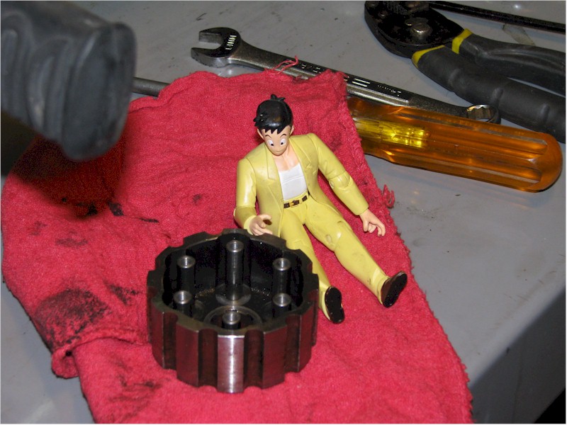
Next you can remove the large outer clutch hub:
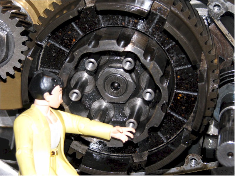
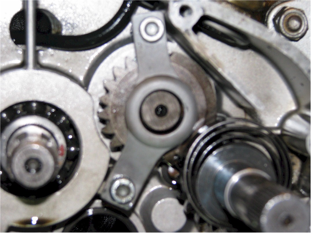
Now you have access to the troublesome leaf spring:
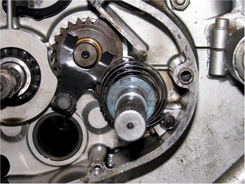
Back out the single bolt at the bottom of the leaf spring and
remove the bolt and spring:

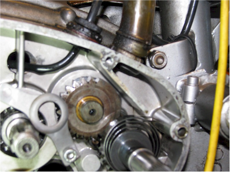
Secure the bottom of the coil spring bridge bridge in the
existing hole that the leaf spring used. There is a small spacer that goes
between the bottom of the coil spring bridge and the engine case hole:
Don't put the spring in yet. You are now just going to figure out where to drill and tap the hole for the upper bridge mount. I will tell you how I did it, you can do it any way you see fit.
Note that the long spacer likely has been chamfered on one end so as to prevent it from hanging up on a boss of the engine case. The chamfered end of the spacer goes toward the engine with the chamfer facing down such that the chamfer sits atop the engine case boss.
I took a drill bit just slightly smaller than the inside
diameter of the long spacer. I placed the drill bit though the upper
bridge hole and then through the long spacer.
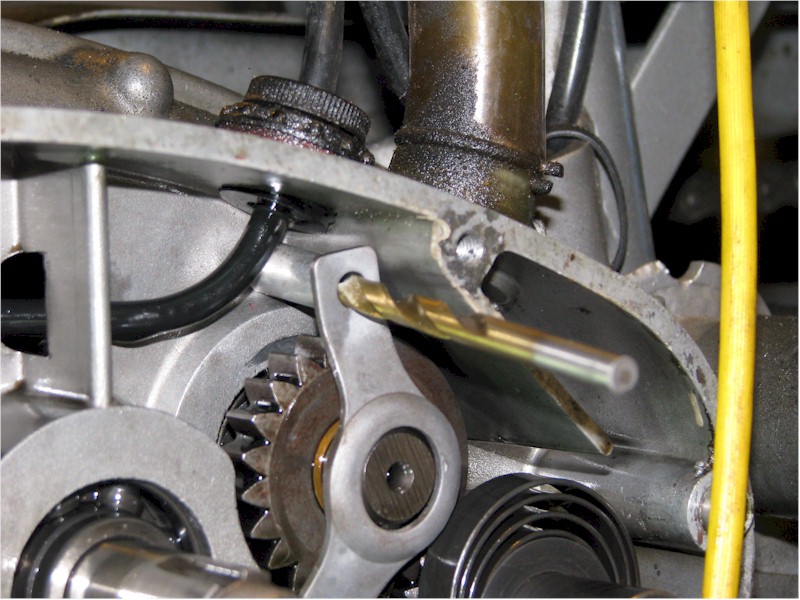
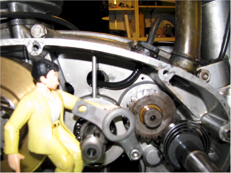
I carefully positioned the large center bridge hole over the
kick-start gear hub. Holding both the bridge in position and the long
spacer flush to the back of the bridge with the chamfer facing downward, I
twisted the drill when I was satisfied with the alignment so as to make a mark
on the engine case. In the photo you can see the tiny mark just above the
engine boss:

Now it's time to tap drill for a M6-1.0. I used a shop
rag to keep metal shavings from the drilling out of the engine as best I could.
I also often stopped and used a shop vacuum to suck up the shavings. I
also used the sticky side of masking tape to capture shavings.
Drill completely through the case:
Now it's time to tap the hole for the M6-1.0 bolt. I
went slowly, cleaning the tap threads often:
With the hole tapped you can now place the spring behind the
bridge.
You will put the bolt through the bridge and through the
spacer which should be between the bridge and the engine case. Make sure
the chamfered end of the spacer is toward the engine. Make sure the
chamfer faces downward so as to prevent the spacer and engine boss from
interfering with each other. I found that my chamfer was a bit undercut,
and so I had to grind it some so as to eliminate some mechanical conflict that
prevented the spacer from standing straight away from the engine case.
Tighten up both the top and bottom bridge bolts. Use
some Loctite blue.
Re-assembly is simply the reverse procedure, and remember to put a locking tab on the clutch hub center nut.
I simply used the impact gun to tighten the clutch nut.
My success was largely a result of forum member help throughout the planning and implementation and for this I am appreciative.