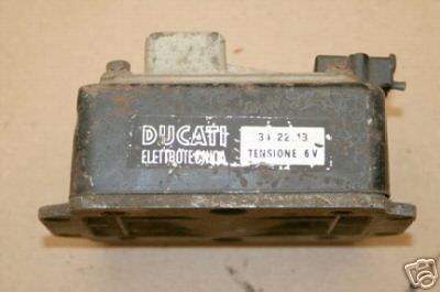
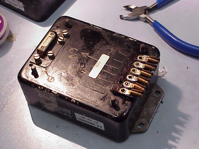
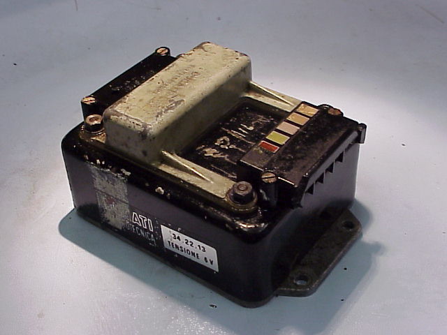
Ducati 6V regulator purchased on eBay described as "Condition unknown low miles bike."
The regulator will be disassembled with the intent to verify its functionality before being used in a Mach 1 restoration in New Zealand.
If any problems are detected a repair will be attempted.

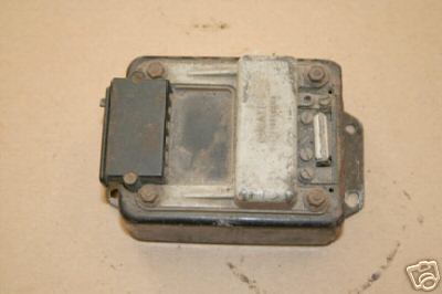
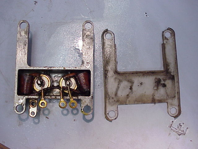
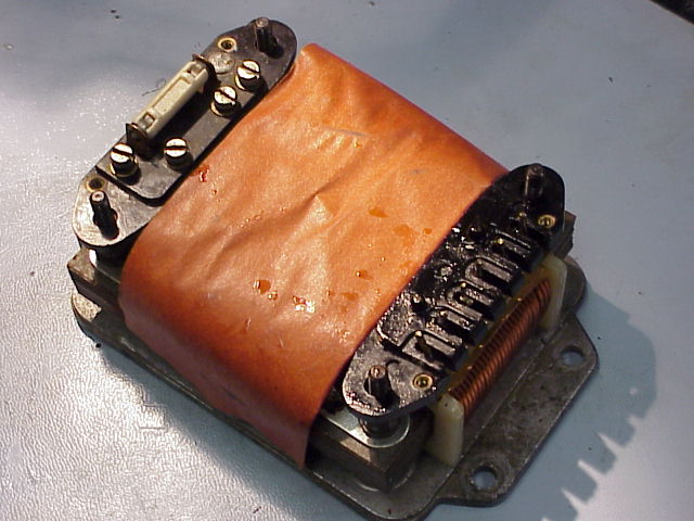
The regulator of unknown condition sits next to a new old stock regulator for comparison.

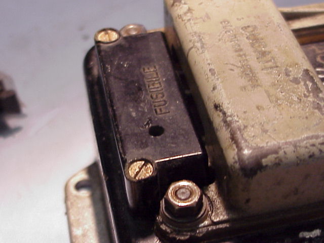
The eBay regulator is missing the fuse cover. The fuse was later found in the bottom of the shipping box amongst the packing peanuts.

The eBay regulator has dents in metal box.
Dents were found in two corners.
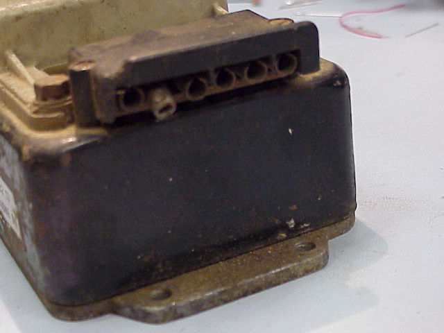
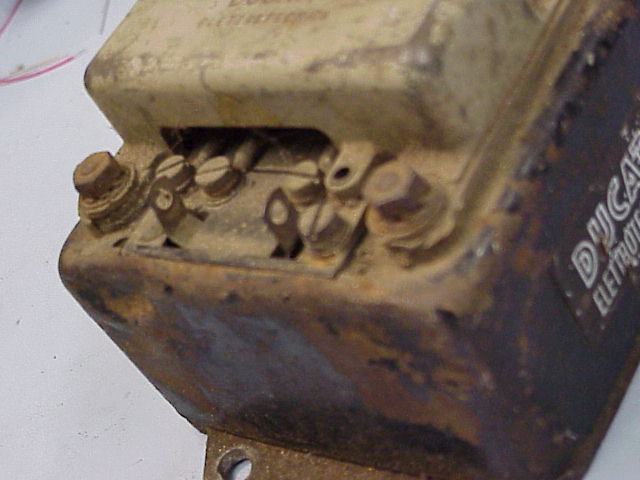
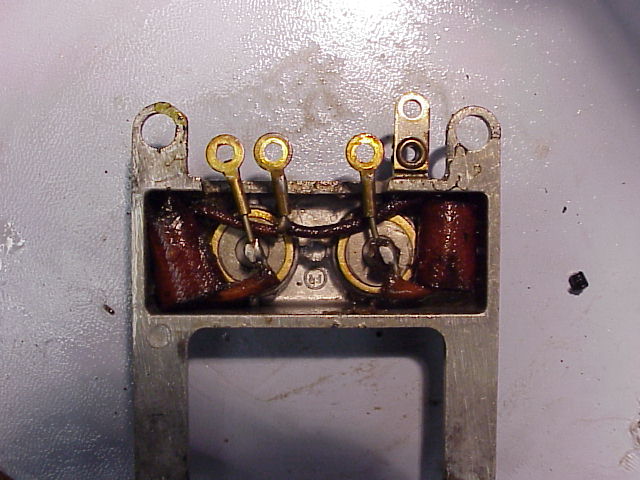
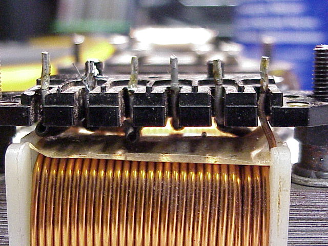
Something looks wrong with the terminal block.
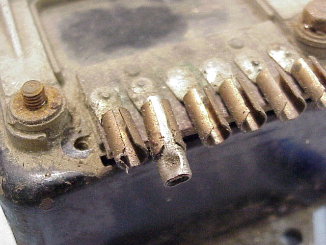
As it turns out this is not a problem, just a broken-off connector shell in the terminal input/output block.

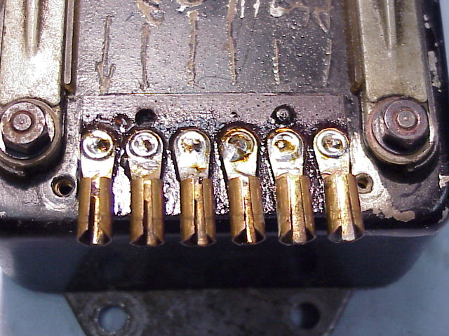
Here is a problem though - the vanes are all cracked off. The vanes are supposed to keep the phenolic terminal input/output block's metal barrels from rotating and shorting to each other.

Initial disassembly:
1) The terminal input/output block cover is removed with two screws on either side. The terminal input/output block must then be cleaned of solder with solder wick or a solder sucker for removal. The terminal input/output block with connector barrels can be lifted off.
Be careful to lift straight up on the terminal block to avoid breaking two small alignment pins on the comb.
2) Four nuts hold the "H" shaped heat sink on physically. Be careful as there are nylon spacers with collars in the heat sink holes that are used to electrically isolate the heat sink from the metal box. The sequence of fasteners is nut, lock washer, flat washer and then nylon collar washer. If the nuts on the underside of the regulator box should begin to rotate when trying to remove the heat sink, you will need to wedge something small against the recessed underside nuts such that they will not turn and iit will be the top nuts that rotate off.
3) The four electrical connection screws in-between the short legs of the "H" must be backed out and then lift the heat sink off. Be careful to retain thee small lock and flat washers under the these screws.
The diodes are mounted in the "H" shaped heat sink. Note that there is an "H" shaped nylon insulator that mounts on the bottom of the heat sink against the box, again for electrical isolation.
4) The metal box lid can then be lifted off.
5) The "comb" under the terminal block will now also lift off.
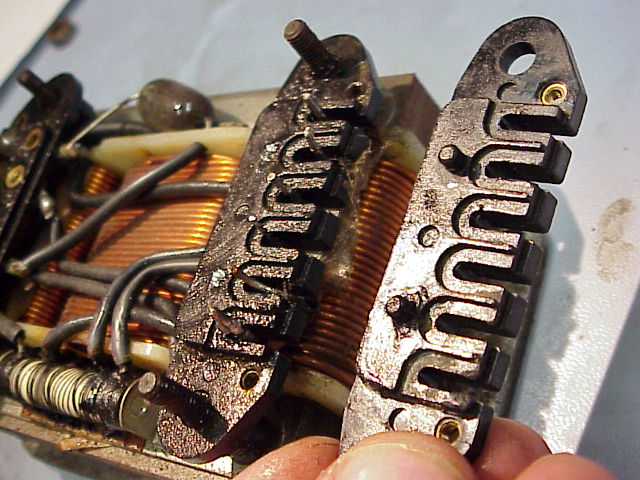
Here is another problem: the "comb" that separates the wires heading into the phenolic terminal block that I am holding has two pegs for alignment of the terminal block. The eBay regulator's alignment pins were sheared off and lodged in the phenolic terminal block.

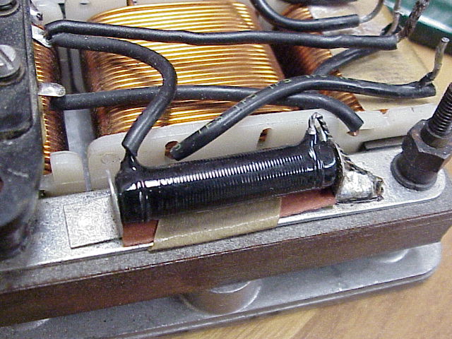
The cylinder in the foreground of the regulator is a 27 ohm 3-watt wire wound resistor, but there is something visibly wrong with the resistor. It shows signs of having had too much current pass through it and having become too hot.
The cylinder at the opposite side of the resistor on the regulator frame is the high frequency filter capacitor.
For reference, this is what a good resistor should look like. This frame will be used for the rebuild of this regulator.
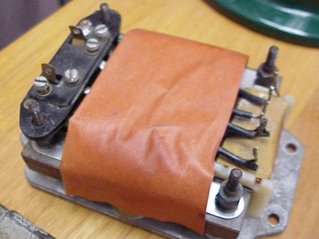
There should have been an insulating paper sheet like the one shown above in the regulator, but it wasn't there. It could be that it was neglected at the time of manufacture.
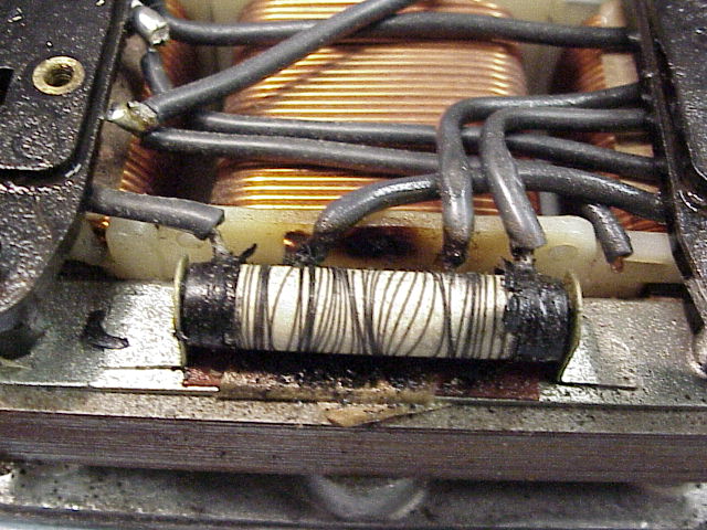
A closer look at the burned up resistor. Notice the heat discoloration on, behind and underneath the resistor. Looking inside the metal cover reveals heat discoloration there as well.
On the left you see the heat sink and on the right in the insulating plastic that goes between the heat sink and the metal regulator box.
There are four diodes of two different styles in the heat sink. Two high power diodes are cylindrical and are pressed into the heat sink for thermal conductivity, the other two are under brown insulating sleeves.
Trying to find a replacement
diode in a metal can of the correct diameter and depth that matches an item made in Italy 40 years ago might be 'difficult.' The diodes
are designed to make
full contact the heat sink to help dissipate their heat.
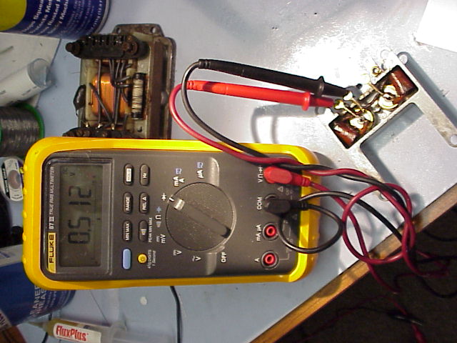
Testing the diodes
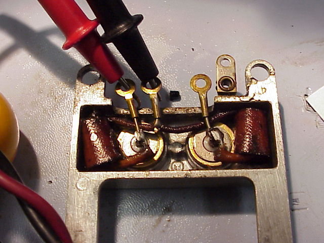
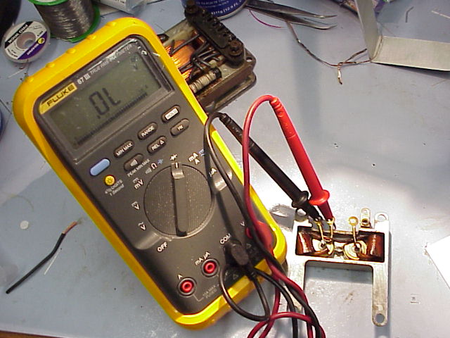


The diodes have been verified as good and the rebuild will not take place. The frame shown earlier with the good resistor will be used as the basis for this particular refurbishment.
The comb can then be placed over the wires to align them for later connection to the terminal input/output block.
The paper insulating sheet is placed over the chokes built into the regulator core.

The metal box is now placed over the frame.
The terminal input/output block can be set over the tops of the wires that are separated by the comb.

The heat sink is placed on next. Note that plastic isolator is placed in-between the heat sink and the metal regulator box. The plastic collar washers are then put in place, collars down.

The heat sink is then bolted down. The top down sequence is bolt, lock washer, flat washer and plastic collar washer with the collar facing down.
The fuse cap is then mounted on.
The terminal input/output strip is now soldered in place.
Refurbishing completed. I believe that Road and Race in Australia sells reproduction color bar strips for above the terminal input/output block. Road and Race may also have reproduction stickers for the sides of the regulator as well.